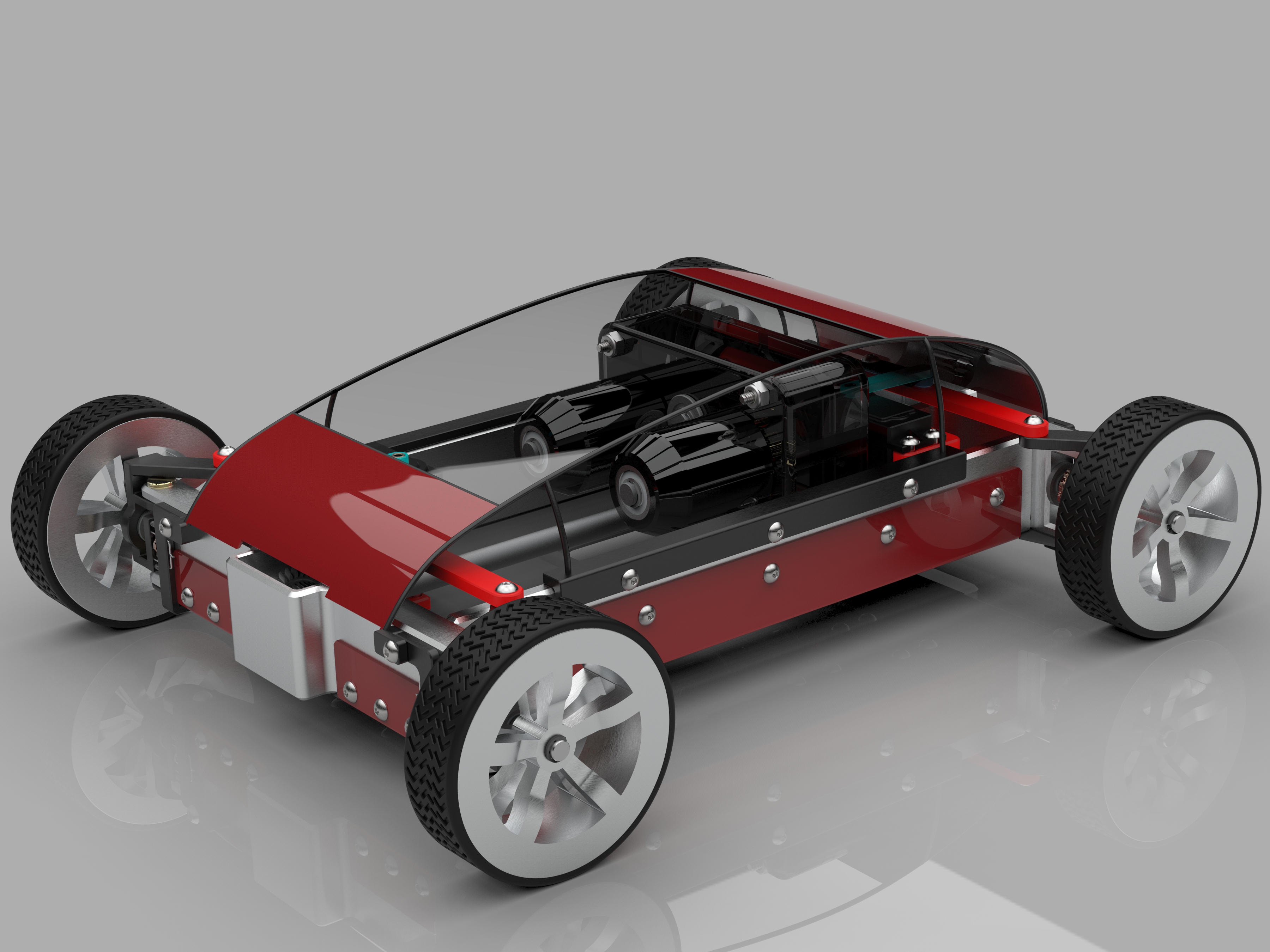
RC Car Model

Introduction
This project was a purely CAD-based one, and I completed for an introductory CAD course at my university. I picked an RC car because it balanced simplicity with flexibility well, which gave me a solid base for completing the project within the firm deadline while affording me room to experiment and grow my CAD skills. Further, an RC car meant that packaging was very important because of the tight space constraints, and I find mechanical packaging to be an enjoyable challenge.
Goals
I wanted to implement Ackermann steering linkages on the front and rear sets of wheels, with a four-wheel drive powertrain. This required the use of two independent differentials, and the powertrain utilized two brushless DC motors and a two-stage gearbox. Because these spur and bevel gears would be designed from scratch, this project gave me an opportunity to dive more deeply into gear design so that I could model my own. Additionally, I wanted to use mechanical disc brakes on all four wheels, which demanded that the brake assemblies be very small, further reinforcing the packaging aspect discussed in the introduction.

Design Process
I began by sketching a layout of the car and its powertrain, which gave me an idea of how large the vehicle would need to be to accommodate all of the aforementioned goals. Further, this sketch allowed me to develop the Ackermann linkage geometry, which turned out to be one of the most challenging aspects of this project. Ideally, an Ackermann linkage is designed such that lines drawn normal to the two wheels it controls intersect at a common point - with fixed rear wheels, this common point is usually along the axis of the rear axle, and with dual-steering, the pair of linkages usually intersect on a lateral line drawn through the middle of the vehicle. However, designing a pair of linkages to exactly fit this constraint for every point along a line - which is referred to as a perfect Ackermann linkage, where the tie rod does not change in length over a fixed turning axis - is very difficult to achieve, so I instead iterated through linkage geometries with the intent to minimize the difference between tie rod lengths over the whole turning span. This meant that, at extreme turning angles, there would be a minute amount of slip because of the imperfect geometry, but those angles would only be used at low speeds where slip is not catastrophic, and the minimization meant that this slip would be fairly small in practice.
One of the other major challenges I encountered in this project were the bevel gears for the differentials. Bevel gear dimensions are driven by a substantial number of input parameters, such as mating angle, tooth pitch, the size of each gear, and the pressure angle of the teeth, among others. This made computing these dimensions very tedious and error-prone, so I wrote a script in MATLAB that requested input parameters, applied the relevant bevel equations to those parameters, and then returned the resulting dimensions for a given bevel gear pair. This substantially expedited the gear design process, and it provided a repeatable method for generating bevel gear designs.

Lessons Learned
I learned and applied quite a lot of information about linkage geometry - and how it applies to vehicles specifically - and gear design in this project, which were deeper conceptual dives than I had been exposed to in previous projects. Further, I experimented with more complex modeling techniques in parts like the car wheels and aero shell, and designing parts that I would otherwise simply download an off-the-shelf model for gave me some additional practice in interpreting and converting mechanical drawings.
