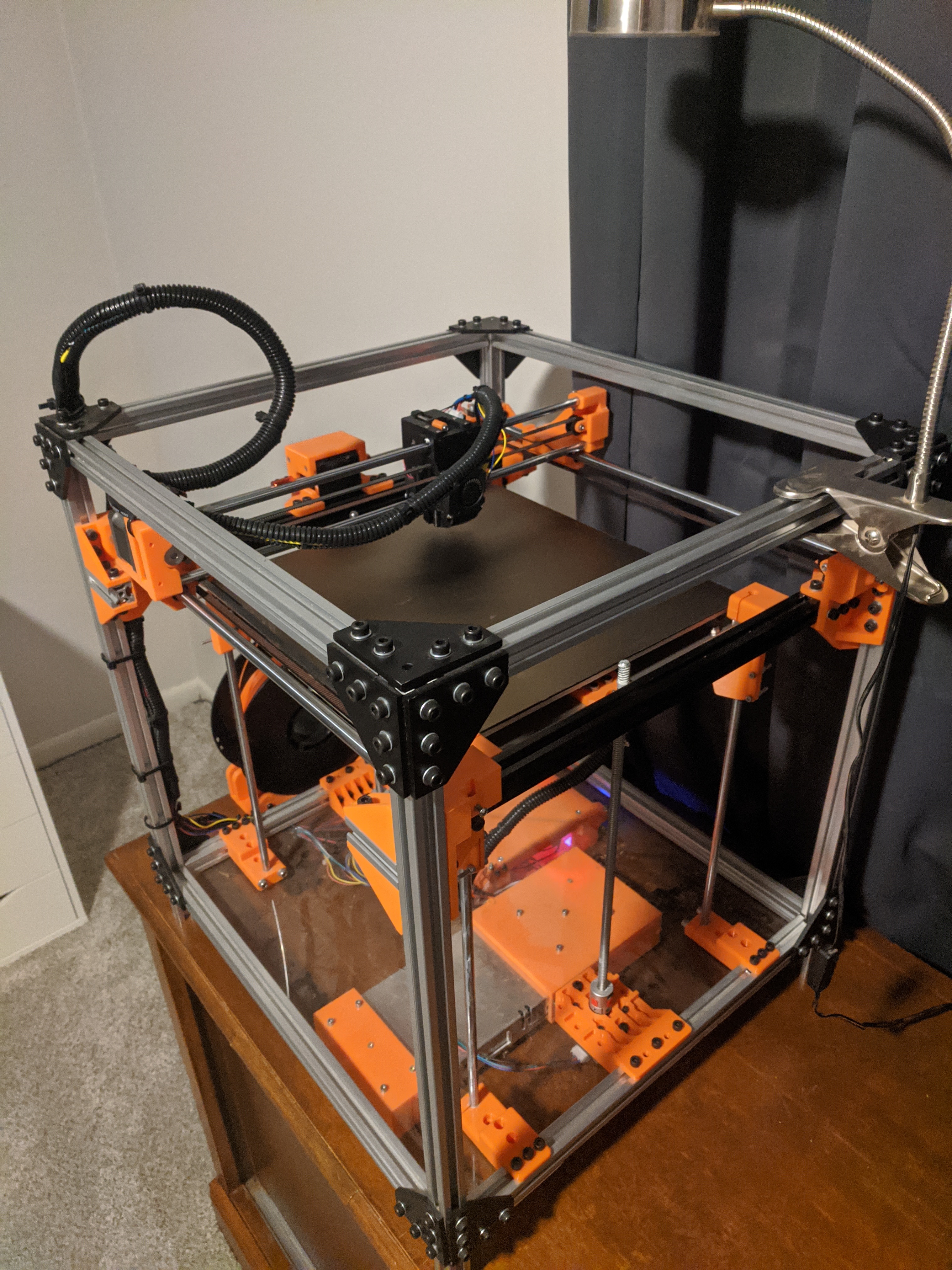
Custom 3D Printer

Introduction
In December 2020, as a response to the COVID-19 pandemic preventing me from accessing tools and fabrication equipment at my university, I began designing a custom FDM 3D printer to meet my needs and constraints. The biggest constraint for this project was related to the footprint of the machine; Due to storage limitations, I wanted to maximize the build volume while minimizing the overall footprint, and I wanted the build volume to be fully contained within the footprint. This eliminated the very popular i3 approach, which moves the print bed back and forth while raising a gantry, because the bed usually extends beyond the perimeter of the machine. As such, I was left with a decision between two options. The first was a cartesian format, where the bed acts as the vertical (z) axis while the extruder assembly moves on a 2-axis gantry. The second is known as “CoreXY”, where a pair of motors and belts provide the same 2-axis gantry motion, albeit with significant weight-savings. However, the CoreXY approach is much more sensitive to precision deficiencies in manufacturing (due to its more complex kinematics), so I opted for the cartesian approach while leaving an intentional upgrade path to CoreXY for the future, if I decided to do so. This solution provided the contained footprint that I was pursuing, and the frame design lends itself well to a very flexible and easily-upgradeable machine.
Design Considerations
In addition to the footprint constraints, I wanted to be able to use this machine for fairly large projects, which necessitated the build volume maximization outlined in the introduction. There was little space to waste where I intended to store this machine, so every added inch to the footprint had to bring something valuable along with it. Further, I wanted the thermal and acoustic outputs to be tolerable, so I designed the frame to readily accept enclosure panels in the future. This upgrade would make the thermal environment more efficient and stable, and it would provide some degree of noise isolation from the fans and stepper motors. Finally, I wanted this build to be at least somewhat cost-effective, relative to off-the-shelf solutions, so I used commonly-available parts wherever possible.
Design Process
As with most other projects, I began designing with brainstorming and 2D sketches in SolidWorks, which allowed me to rapidly iterate on the rough footprint and printer format - this step is where I decided on a cartesian motion system - and answer many of my initial questions. This step gave me a direction to work off of, and I started designing the frame soon after. While I had a hard constraint on the maximum machine footprint, I was unsure exactly how that would translate into build volume, so I worked around that question until I developed a better sense of how much space the printer would need outside of the usable build area. I did this by working with more sketches to plan out the rough locations of various components in relation to the frame and one another. From this, I determined that, with enough optimization work, I could achieve a 310x310mm build area while staying inside the maximum frame dimensions. Once this question was nailed down, I worked on modeling the individual axes according to the newly-determined space constraints. While those were fairly simple problems to solve, the extruder design took far and away the most time out of any single assembly for the whole system. Keeping the size of the extruder down was crucial for fitting within the footprint, and packaging on such a small assembly turned out to be very challenging; the extruder assembly contained the hotend, a motor and extruder gears, a bed-leveling induction probe, a pair of cooling fans, and geometry for translating the extruder along one of the axes via belts.

Assembly & Challenges
Because of the COVID-19 pandemic, stock shortages and shipping delays were major issues while acquiring parts for this project. Parts slowly trickled in over the course of weeks and months, so the project remained stalled for much of spring 2021. Over the summer, I began assembling the machine and most of it went smoothly. The biggest issues I encountered were related to tolerance stackup - many of the tools I had access to for this project were fairly imprecise - on the frame extrusions and in the extruder assembly, but both were fixed with careful measurements and some sanding where necessary. After that, an issue with the print bed rigidity required a minor revision. Originally, I had dedicated just one linear bearing per rod (for a total of four) for the bed for fear of overconstraining it, but this resulted in too much wobble in the bed, and this wobble led to binding issues. Revising the system to use two bearings per rod meant that the vertical build axis lost about 24mm of travel, but it resulted in a far more precise, and binding-free, bed.
Upgrades for the Future
Unfortunately - although not entirely suprisingly - the hotend cooling fan performed worse than desired and the extruder exhibits some amount of “heat creep,” where heat from the hotend travels up into the heatsink and softens the filament prematurely, leading to inconsistent extrusion. I’ve since designed a revision for the extruder that substantially simplifies the flow path for the air and utilizies a fan with higher airflow and static pressure, and I’m currently waiting on parts before assembling and testing that revision.
I’d also like to implement better wire management throughout the printer, from more effective strain-relief on the extruder cables to drag chains on the gantry axes for more repeatable cable motion. I intend to print these upgrades with the printer itself and implement them soon after the aforementioned extruder upgrade.
Finally, I intend to add enclosure panels to the printer once the systems have seen more use and the early revisions are out of the way. This will improve print quality and reduce noise levels from the printer.
Lessons Learned
This project was a fantastic lesson in tolerance stackups for less-precise fabrication methods, and it taught me methods for designing around wider manufacturing tolerances and when to recognize where the required precision for a design is infeasible. Additionally, I learned about fluid mechanics and thermal design while designing the extruder assembly, and I applied skills from my mechanics courses (statics, mechanics of materials, etc.), such as drawing and analyzing free-body diagrams, when working to solve the bed wobble issue discussed in the Assembly & Challenges section.
